
Introduction :
Logic gates are the digital electronics devices (or) circuits, which accepts one (or) more number of inputs, but gives only one number of output.
Why do we need logic gates in the first place? Logic gates are the building blocks for the modern digital computation. With the help from the logic gates, any kind of logic functions can be performed. There are so many different types of logic gates, These are classified depends on their logical operations, ( EX-OR, EX-NOR )among them some are classified as Basic logic gates ( AND, OR, NOT ) and some are classified as Universal logic gates ( NAND, NOR ) . Here the NOR logic gate is classified as Universal logic gate. The electronic circuit which performs this NOR logic function is called NOR logic gate.
Logic gates are the basic building blocks, for all the modern day digital electronics devices.
NOR logic gate :
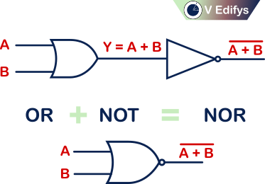
The logic behind the NOR logic gate is, “If any one of the inputs to a logic gate is logic high, then it’s output is logic low”. These type of logic gate is known as NOR logic gate.
It’s operation is equivalent to the complement of logic OR gate.
i.e.
What is meant by logic high?
Here logic high means the input voltage of one of the inputs is slightly higher than the input voltage of the other inputs. The most common logic high input voltages are (+5 V, +1 V, +3.3 V etc.,). In digital terms logic high is represented as “1” in positive logic and as “0” in negative logic. In digital terminology “1” is not a mathematical constant one (1), it’s just a representation of logic high state in positive logic, similarly “0” is not a mathematical constant zero (0), it’s just a representation of logic high state in negative logic.
In Boolean algebra term,
logic high = 1 = high voltage ( positive logic )
logic high = 0 = high voltage ( negative logic )
What is meant by logic low?
Here logic low means the input voltage of one of the inputs is slightly lower than the input voltage of the other inputs. The most common logic low input voltages are ( 0 V, -5 V, -3.3 V, -1 V etc.,). In digital terms logic low is represented as “0” in positive logic and as “1” in negative logic. In digital terminology “0” is not a mathematical constant zero (0), it’s just a representation of logic low state in positive logic, similarly “1” is not a mathematical constant one (1), it’s just a representation of logic low state in negative logic.
In Boolean algebra term,
logic low = 0 = low voltage ( positive logic )
logic low = 1 = low voltage ( negative logic )
Note :
- NOR logic is same as the complement of binary addition.
- Any open ended input is treated as logic “0” in Positive logic NOR gate.
- Any open ended input is treated as logic “1” in Negative logic NOR gate.
Universal logic gates :
NAND gate and NOR gate are called as Universal logic gates. Why are they called as Universal logic gates?
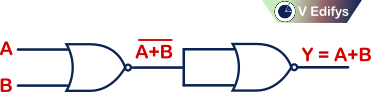
Any logic function (or) logic gate can be created by using only the NAND (or) NOR logic gates. This is why these gates are called as Universal logic gates.
Ex :
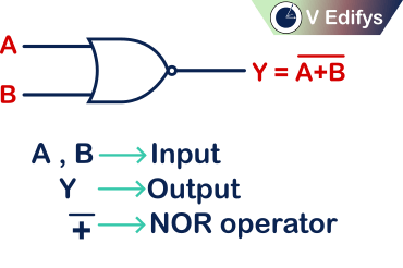
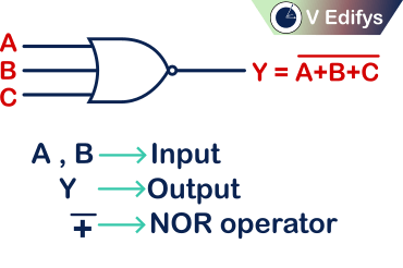
NOR operator :
NOR operator is represented as “ ![]() ”, Read it as “NOR”. It is represented by an overline placed above OR operator. It acts like a complement of binary addition.
”, Read it as “NOR”. It is represented by an overline placed above OR operator. It acts like a complement of binary addition.
EX :
Boolean Expression = ![]() , Read it as A “NOR” B
, Read it as A “NOR” B
Classification of logic NOR gates :
NOR gates are classified depends upon their number of inputs. The most commonly used NOR gates are
- Two input logic NOR gate.
- Three input logic NOR gate.
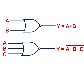
Two input logic NOR gate :
If a NOR logic gate, which accepts two inputs and provide the desired NOR logic as output then that type of logic gate is called as Two input logic NOR gate.
It’s logic function is,
Positive logic :
“When all the inputs is logic low (0), only then the output is logic high (1)”.
Positive logic gates are widely used.
Negative logic :
“When all the inputs is logic low (1), only then the output is logic high (0)”.
Logic Symbol :
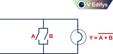
Switch representation :
If,
n = number of switches (inputs)
m = maximum possible number of output combination

Ex :
number of inputs (n) = 2
Maximum possible number of output combination (m) = 22 = 4
Truth table :
Positive logic :
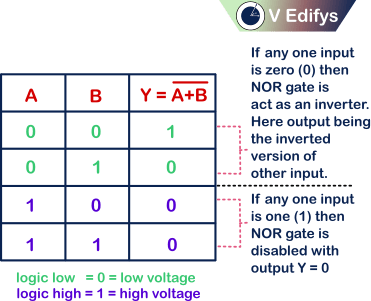
If any one input is,
0 = NOR gate is act as an inverter with output is the inverted version of the other input.
1 = NOR gate is disabled with output is zero (0).
Positive logic NOR gate is equals to the Negative logic NAND gate
Unused input :
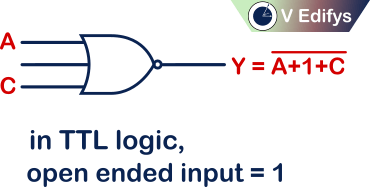
TTL logic :
In TTL logic, if any input is open (or) floating, it will act as “1”
ECL logic :
In ECL logic, if any input is open (or) floating, it will act as “0”
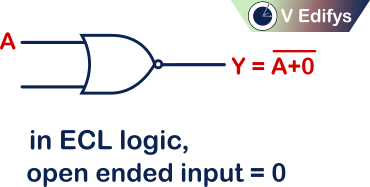
In positive logic NOR gate, the open (or) floating input follows ECL logic, which means open (or) floating input in Positive logic NOR gate is considered as “0”.
Negative logic :

If any one input is,
0 = NOR gate is disabled with output is one (1).
1 = NOR gate is act as a inverter with output is the inverted version of the other input.
With this we can say that,
Negative logic NOR gate is equals to the Positive logic NAND gate
Unused input :
TTL logic :
In TTL logic, if any input is open (or) floating, it will act as “1”
ECL logic :
In ECL logic, if any input is open (or) floating, it will act as “0”

In negative logic NOR gate, the open (or) floating input follows TTL logic, which means open (or) floating input in Negative logic NOR gate is considered as “1”.
Three input logic NOR gate :
If a NOR logic gate, which accepts three inputs and provide the desired NOR logic as output then that type of logic gate is called as Three input logic NOR gate.
It’s logic function is,
Positive logic :
“When all the inputs is logic low (0), only then the output is logic high (1)”.
Positive logic gates are widely used.
Negative logic :
“When all the inputs is logic low (1), only then the output is logic high (0)”.
Logic Symbol :
Switch representation :

If,
n = number of switches (inputs)
m = maximum possible number output of combination
Ex:
number of inputs (n) = 3
Maximum possible number of output combination (m) = 23 = 8
Truth table :
Positive logic :
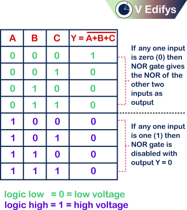
If any one input is,
0 = NOR gate gives NOR of the other two inputs as output..
1 = NOR gate is disabled with output is zero (0)
With this we can say that,
Positive logic NOR gate is equals to the Negative logic NAND gate
Unused input :
TTL logic :
In TTL logic, if any input is open (or) floating, it will act as “1”
ECL logic :
In ECL logic, if any input is open (or) floating, it will act as “0”
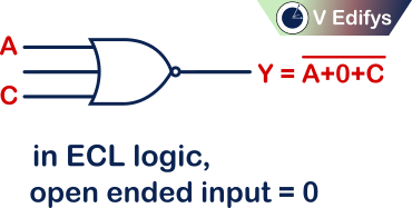
In positive logic NOR gate, the open (or) floating input follows ECL logic, which means open (or) floating input in Positive logic NOR gate is considered as “0”.
Negative logic :
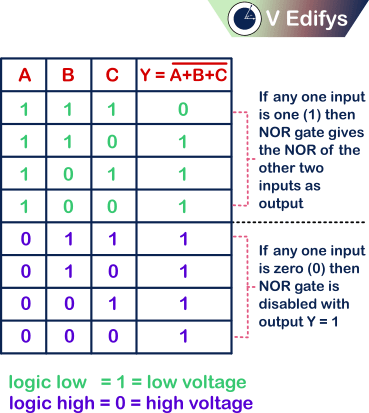
If any one input is,
0 = NOR gate is disabled with output is one (1).
1 = NOR gate gives NOR of the other two inputs as output.
With this we can say that,
Negative logic NOR gate is equals to the Positive logic NAND gate
Unused input :
TTL logic :
In TTL logic, if any input is open (or) floating, it will act as “1”
ECL logic :
In ECL logic, if any input is open (or) floating, it will act as “0”
In negative logic NOR gate, the open (or) floating input follows TTL logic, which means open (or) floating input in Negative logic NOR gate is considered as “1”.
Boolean law :
NOR gate is following this Boolean law.
- Commutative law :
This law states that, the complement of binary addition of the two inputs is equivalent to the complement of binary addition performed by changing the order of the same inputs.
i.e.
where, A & B are logic inputs.
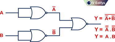
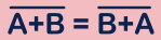
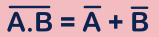
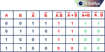
De Morgan’s law :
Logical NAND operation between the two inputs is equals to the logical OR operation of the complemented version of the same two inputs.
i.e.
where, A & B are logic inputs.
In other words,
Logical NOR operation between the two inputs is equals to the logical AND operation of the complemented version of the same two inputs.
i.e.

where, A & B are logic inputs.
Proof of De Morgan’s law :
Conclusion :
Now we all know, that what is logic NOR gate and how it operates. Logic gates are the basic building blocks for any kind of digital electronic devices/systems. NOR logic gate is known as Universal logic gate, because by using only the NOR logic gate, it is possible to make any kind of digital logical functions.
2 Responses
It is a pleasure to read this weblog, thanks to its up-to-date information and interesting posts.
I’m really impressed with your writing talents as
smartly as with the layout to your blog. Is this a paid topic or did you customize it yourself?
Anyway stay up the excellent high quality writing, it’s
uncommon to peer a nice weblog like this one today.