

Introduction :
Logic gates are the digital electronics devices (or) circuits, which accept one (or) more inputs but give only one output.
Why do we need logic gates in the first place? Logic gates are the building blocks for modern digital computation. With the help of logic gates, any kind of logic function can be performed. There are so many different types of logic gates, These are classified depending on their logical operations, ( EX-OR, EX-NOR )among them some are classified as Basic logic gates ( AND, OR, NOT ) and some are classified as Universal logic gates ( NAND, NOR ). Here the EX-OR logic gate is classified depending upon its logical operation. The electronic circuit that performs this EX-OR logic function is called the EX-OR logic gate.
Logic gates are the basic building blocks, for all the modern-day digital electronics devices.
EX-OR logic gate :
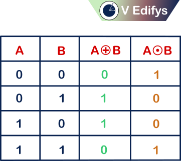
The logic behind the EX-OR logic gate is, “If an odd number of inputs to a logic gate is logic high, then its output is logic high”. This type of logic gate is known as the EX-OR logic gate.
EX-OR logic gate is simply known as “Odd 1’s detector”. It is a complemented version of the logic EX-NOR gate.
EX-OR means Exclusive-OR. It is also represented as a logic X-OR gate.
What is meant by logic high?
Here logic high means the input voltage of one of the inputs is slightly higher than the input voltage of the other inputs. The most common logic high input voltages are (+5 V, +1 V, +3.3 V etc.,). In digital terms logic high is represented as “1” in positive logic and as “0” in negative logic. In digital terminology “1” is not a mathematical constant one (1), it’s just a representation of logic high state in positive logic, similarly “0” is not a mathematical constant zero (0), it’s just a representation of logic high state in negative logic.
In Boolean algebra terms,
logic high = 1 = high voltage ( positive logic )
logic high = 0 = high voltage ( negative logic )
What is meant by logic low?
Here logic low means the input voltage of one of the inputs is slightly lower than the input voltage of the other inputs. The most common logic low input voltages are ( 0 V, -5 V, -3.3 V, -1 V etc.,). In digital terms logic low is represented as “0” in positive logic and as “1” in negative logic. In digital terminology “0” is not a mathematical constant zero (0), it’s just a representation of logic low state in positive logic, similarly “1” is not a mathematical constant one (1), it’s just a representation of logic low state in negative logic.
In Boolean algebra terms,
logic low = 0 = low voltage ( positive logic )
logic low = 1 = low voltage ( negative logic )
Note :
- EX-OR logic is the same as odd 1’s detector.
- If the number of inputs given to the logic EX-OR gate is odd, then the logic operation of the EX-OR logic gate is equal to the logic operation of the EX-NOR logic gate.
- If the number of inputs given to the logic EX-OR gate is even, then the logic operation of the EX-OR logic gate is an inverted version of the logic operation of the EX-NOR logic gate.
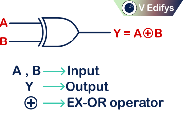
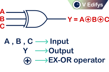
EX-OR operator :
EX-OR operator is represented as “ ![]() “. Read it as “EX-OR”. It is represented as a plus (or) addition operator surrounded by the circle. It acts like odd 1’s detector.
“. Read it as “EX-OR”. It is represented as a plus (or) addition operator surrounded by the circle. It acts like odd 1’s detector.
EX :
Boolean Expression = ![]() , Read it as A “EX-OR” B
, Read it as A “EX-OR” B
Classification of logic EX-OR gates :
EX-OR gates are classified depending on their number of inputs. The most commonly used EX-OR gates are
- Two input logic EX-OR gate.
- Three input logic EX-OR gate.
Two input logic EX-OR gate :
If an EX-OR logic gate accepts two inputs and provides the desired EX-OR logic as output then that type of logic gate is called a two-input logic EX-OR gate.
Boolean logical Expression,

Its logic function is,
Positive logic :
“When both of the inputs are different, i.e. one of the inputs is logic high (1) and the other one is logic low(0) (or) vice versa, only then the output is logic high (1)”. Positive logic gates are widely used.
Negative logic :
“When both of the inputs are different i.e. one of the inputs is logic high (0) and the other one is logic low(1) (or) vice versa, only then the output is logic high (0)”.
Logic Symbol :
Switch representation :
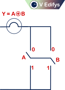
If,
n = number of switches (inputs)
m = maximum possible number of output combination

Ex :
number of inputs (n) = 2
Maximum possible number of output combination (m) = 22 = 4
Truth table :
Positive logic :
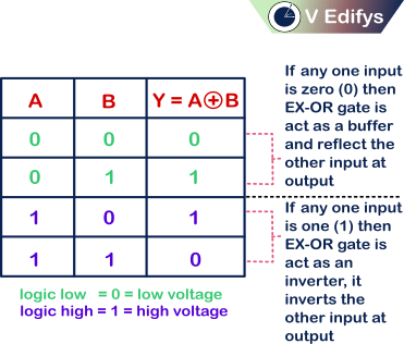
If any one input is,
0 = EX-OR gate acts as a buffer with the output being the other input.
1 = EX-OR gate acts as an inverter with output being the inverted version of other input.
With this, we can say that,
Positive logic EX-OR gate is equal to the Negative logic EX-NOR gate
Negative logic :
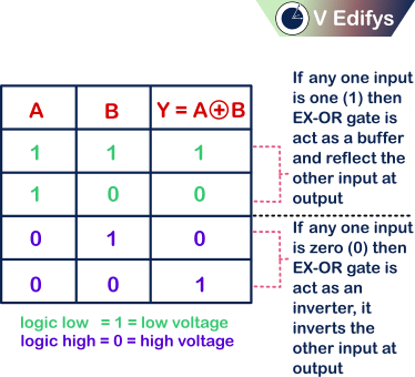
If any one input is,
0 = EX-OR gate acts as an inverter with output being the inverted version of other input.
1 = EX-OR gate acts as a buffer with the output being the other input.
With this, we can say that,
Negative logic EX-OR gate is equal to the Positive logic EX-NOR gate
Unused input :
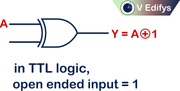
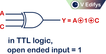
TTL logic :
In TTL logic, if any input is open (or) floating, it will act as “1”
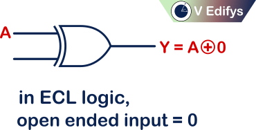
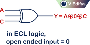
ECL logic :
In ECL logic, if any input is open (or) floating, it will act as “0”
Three input logic EX-OR gate :
If an EX-OR logic gate accepts three inputs and provides the desired EX-OR logic as output then that type of logic gate is called a three-input logic EX-OR gate.
Boolean logical Expression,

Its logic function is,
Positive logic :
“When an odd number of the inputs is logic high (1), only then the output is logic high (1)”. Positive logic gates are widely used.
Negative logic :
“When an odd number of the inputs is logic high (0), only then the output is logic high (0)”.
Logic Symbol :
Switch representation :
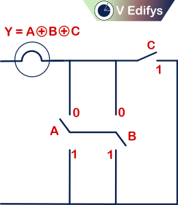
If,
n = number of switches (inputs)
m = maximum possible number output of combination
Ex:
number of inputs (n) = 3
Maximum possible number of output combination (m) = 23 = 8
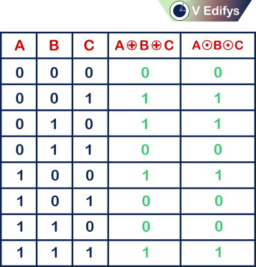
Truth table :
Positive logic :
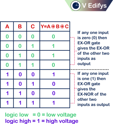
If any one input is,
0 = EX-OR gate gives EX-OR of the other two inputs as output.
1 = EX-OR gate gives EX-NOR of the other two inputs as output.
With this, we can say that,
Positive logic EX-OR gate is equal to the Positive logic EX-NOR gate
Negative logic :

If any one input is,
0 = EX-OR gate gives EX-NOR of the other two inputs as output.
1 = EX-OR gate gives EX-OR of the other two inputs as output.
With this, we can say that,
Negative logic EX-OR gate is equal to the Negative logic EX-NOR gate
Unused input :
TTL logic :
In TTL logic, if any input is open (or) floating, it will act as “1”
ECL logic :
In ECL logic, if any input is open (or) floating, it will act as “0”
Boolean law :
EX-OR gate follows all these Boolean laws.
- Commutative law :
This law states that the logical EX-OR operation between the two inputs is equivalent to the logical EX-OR operation performed by changing the order of the same inputs.
i.e.

where, A & B are logic inputs.
- Associative law :
This law states that if we have three logic inputs, then the logical EX-OR between the logical EX-OR of the second and third logic input, to the first logic input, is equal to the logical EX-OR between the logical EX-OR of the first and second logic input, to the third logic input.
i.e.

where, A,B & C are logic inputs.
Statements proof :
Statement 1 :
If the number of inputs given to the logic EX-OR gate is even, then the logic operation of the EX-OR logic gate is an inverted version of the logic operation of the EX-NOR logic gate.
Proof 1 :
Statement 2 :
If the number of inputs given to the logic EX-OR gate is odd, then the logic operation of the EX-OR logic gate is equal to the logic operation of the EX-NOR logic gate.
Proof 2 :
Conclusion :
Now we all know, what is logic EX-OR gate and how it operates. Logic gates are the basic building blocks for any kind of digital electronic device/system. Logic EX-OR gate is also mentioned as logic X-OR gate. It acts as odd 1’s detector. EX-OR means Exclusive-OR.